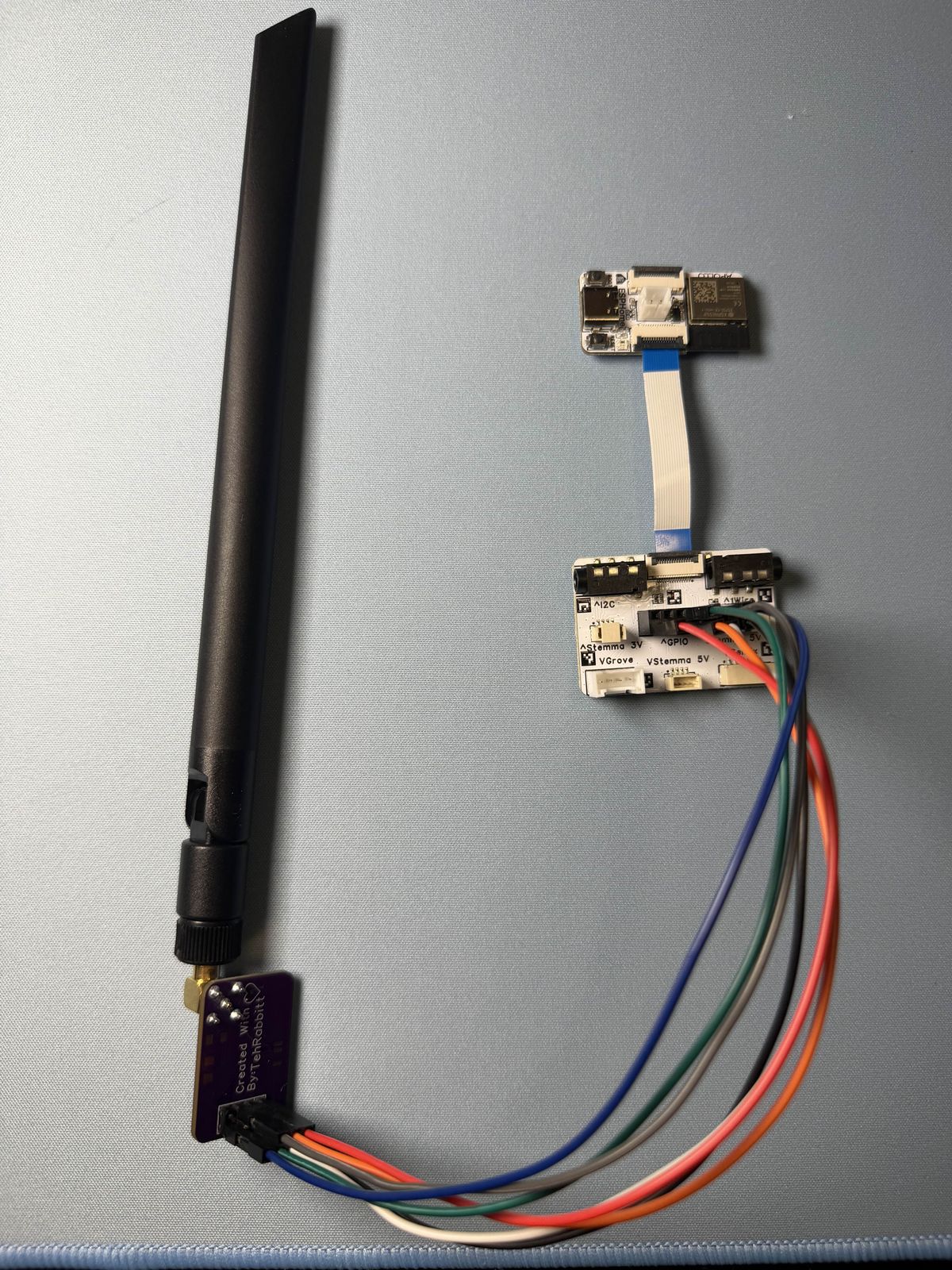
Disclosure: I work for Apollo Automation. The ESPHome Starter Kit and Breakout Module I built this on are our products.
PixMob makes the LED wristbands handed out at concerts and stadium games, the ones that light up together during the show. I got one, and I wanted it to work at home as a normal Home Assistant light.
It does now. It’s an ESPHome external component called esphome-pixmob, and this is what it takes to use it:
external_components:
  - source: github://bharvey88/esphome-pixmob

light:
  - platform: pixmob
    name: "PixMob Band"
    transmitter_id: tx
    cc1101_id: radio
    gamma_correct: 1.0
That’s a real light: entity. Color wheel, brightness, transitions, effects, scenes, automations, voice control, everything Home Assistant gives any other light. Point it at a CC1101 radio and it holds whatever color you pick for as long as you leave it on.
Check which band you have first
This only works on the RF wristbands. Most PixMob bands are infrared, and they will never respond to a radio no matter how it’s configured.
PixMob calls the RF line Waveband. The label on the back of mine reads Product# W2 Gen3, and the board inside is silkscreened CEMENT V1.1. Their X2, X4, X6 and X11 models are all infrared. If you’re buying bands to try this, buy Waveband, and ask the seller for a photo of the label, because listings for stadium giveaways almost never say which model they are.
The frequency follows where the band was deployed rather than where you live: 915.33 MHz in North America, 868.41 MHz in Europe. Neither is a round number. They’re the band’s crystal times 35.
The protocol
The reverse engineering credit here belongs to sueppchen, who worked out the waveband protocol and wrote an Arduino library for it. My work was porting it to ESPHome and documenting what it takes to actually run.
The shape of it: 915.33 MHz, ASK/OOK, 500 microseconds per bit, no Manchester coding. A frame is 90 bits and takes 45 ms. Preamble 0x55 twice, two resync bits, then nine bytes, everything LSB first.
The payload before encoding is seven bytes carrying mode, the three color channels, and the envelope and group fields:
[ mode, green>>2, red>>2, blue>>2, (attack<<3)|random, (release<<3)|hold, group&0x1F ]Two details in there will silently cost you a working frame. Each of those seven bytes is 6b8b line coded through a 64 entry table, and the CRC-12 is then computed over the line coded bytes, not over the original payload. Compute it over the plain bytes and the frame looks perfectly valid on a scope while the band ignores it completely. The color channels are also 6 bits, not 8, which is why the bottom few steps of a brightness slider produce no visible light at all.
The group field is 0 to 31. Bands only respond to their own group, which is how a venue lights sections independently, and it means one transmitter can drive several bands as separate zones.
I wrote all of this up in docs/protocol.md in the repo, so the next person doesn’t have to read C++ to find out what goes on the air.
The part that turns a burst into a lamp
The one thing that makes this feel like a light rather than a party trick: the band forgets its color if it doesn’t hear a frame within about 120 ms.
Send a single frame and you get roughly 3.4 seconds of light followed by a fade. That’s correct behavior for a stadium, where a console blasts frames at thousands of bands all night, and useless for a lamp in a room.
So the component retransmits every 60 ms for as long as the light is on, comfortably inside that window, generating a fresh frame each time from whatever color the light currently holds. Change the color and the next frame carries it, which is why dragging the color wheel tracks live on the band. Turn it off and it sends a few explicit black frames so the band cuts out promptly instead of fading, then puts the radio back in idle.
There are a handful of settings on top of that, all documented with their ranges: group for zones, attack, hold, release and random for the band’s own envelope, plus the refresh interval if you want to tune it.
Documenting it so it’s actually buildable
Reverse engineering something and then writing “wire up a CC1101” helps nobody. The repo has:
- Wiring diagrams for both an ESP32 devkit and an Apollo Starter Kit with the Breakout Module. Both headers are drawn as physical maps with color coded pins, so you match dots rather than parsing sentences about rows and columns.
- Photos of both rigs, wired, with the same wire colors as the diagrams.
- How to identify a compatible band, with a photo of the label and a photo of the board.
- A pin fingerprinting tool, which is the useful one if things go wrong. A CC1101 that reports chip ID
0x0000instead of0x0014is wired wrong, and on modules with unlabeled headers that’s easy to do. The tool samples all four data lines while toggling chip select, and finds GDO0 by the fact that a freshly reset CC1101 idles that pin outputting a clock at about 13.5 MHz. Once you know where GDO0 is, the rest of the header follows. It’s how I sorted out my own module, and it beats a multimeter and guesswork. - Troubleshooting for the failure that isn’t wiring: a solid color that strobes hard at high brightness but is steady when dim, and steady on saturated colors but not on white. That’s the batteries, not the radio. The band runs two CR2032 cells in series and bright white pulls all three LED channels at once, which is enough to make tired cells sag until the band browns out and recovers, over and over. Fresh cells and it’s rock steady.
Which radio module to buy
Worth its own note, because this is the easiest money to waste. The CC1101 chip supports several bands, but any individual board is built for one. TI’s reference design uses one matching network for 868 and 915 MHz and a different one for 315 and 433. Listings titled “315/433/868/915MHZ” are quoting the chip datasheet, not describing the board.
I tested both, same band, same firmware:
- 433 MHz module: works, but only within a few feet in the same room.
- 900 MHz module: works from anywhere in the house, through walls and between floors.
Both light the band, so a 433 board is fine if you just want to prove it works. Only the right band gives you something you can leave on a shelf and forget about.
A blueprint, because a light that only sits there is boring
The component gives you a light. What made it fun was pointing something at it.
TeamTracker is a Home Assistant integration that follows a sports team, and its sensor carries the team’s actual colors as attributes. So the repo also ships a blueprint: when your team scores, the band flashes in your team’s colors, one flash per point. A touchdown flashes six times. Opponent scores get two flashes in their colors if you enable it, kickoff gets three pulses, and the final whistle gets a celebration or a single dim fade. It works with any RGB light, so the band is optional.
Testing that without waiting for a real game meant faking one, so there’s a script that posts a scripted game into a scratch sensor through the Home Assistant API: kickoff, field goal, touchdown, opponent touchdown, another touchdown, final whistle, fifteen seconds apart. The blueprint can’t tell it from the real thing.
What’s in the repo, and what I haven’t proven
It’s BSD licensed, CI compiles it against ESPHome stable, beta and dev, and it’s tested on both an ESP32-C6 and a plain ESP32 WROOM-32 devkit.
The honest limits: one band, one antenna, one house. Everything here is verified against a Cement V1.1 board at 915 MHz and nothing else, so reports from other bands and other regions are welcome. The protocol has modes I haven’t implemented, including writing a band’s group ID over the air, which would turn zones into something you assign from Home Assistant instead of a config value. That’s what I want to do next.
Protocol credit again to sueppchen/PixMob_waveband, and danielweidman/pixmob-ir-reverse-engineering is the best general reference for PixMob hardware, including signal captures for the RF bands.